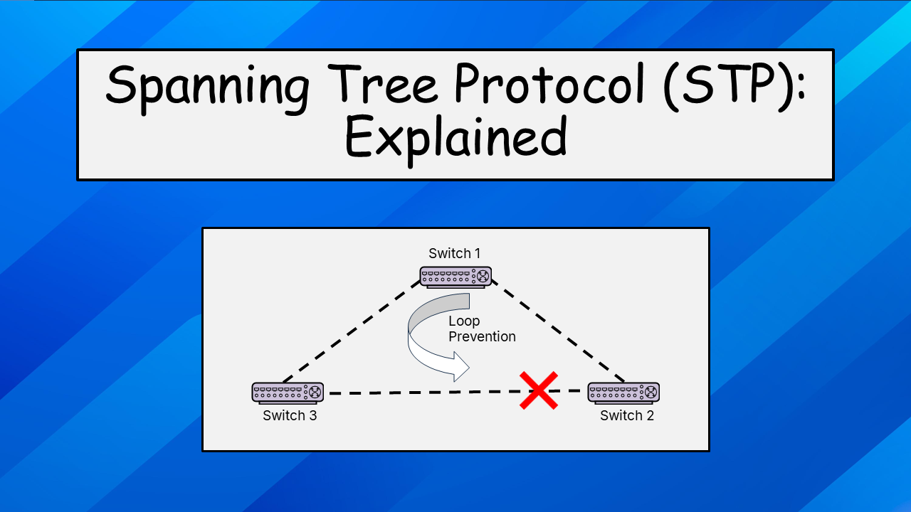
Spanning Tree Protocol (STP): Explained
Learn how STP prevents broadcast loops and keeps networks stable.
Star Topology
Star topology is the most widely used topology in LANs. Home networks almost always use star topology. Enterprise networks also contain star topology, but it is used in conjunction with other typologies (i.e., hybrid topology). All the client devices in a star topology are connected to a central switch, which forwards the packet to its destination.
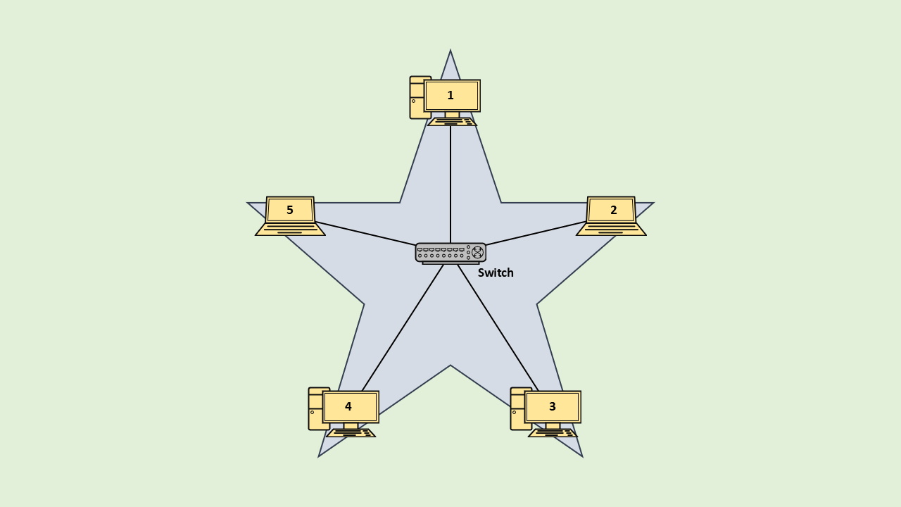
Star is a versatile and robust topology, but it has one major flaw: if the central switch fails, the entire network fails.
Multiple Switches
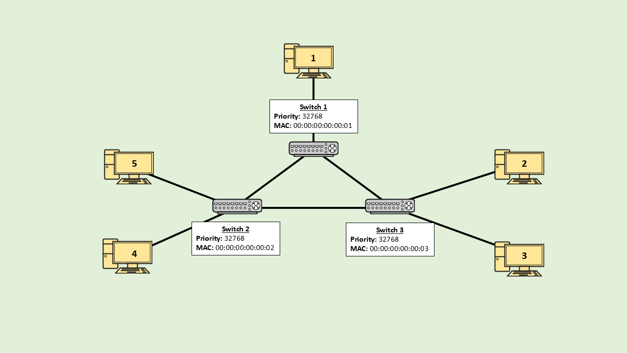
To mitigate the single point of failure, instead of a single switch, multiple switches can be used. This introduces redundancy in the network. Now, even if one of the switches/cables were to fail, the network would continue to operate normally.
In this redundant network, PC 5 has two routes to communicate with PC 3.
Route 1: PC 5 → Switch 2 → Switch 3 → PC 3
Route 2: PC 5 → Switch 2 → Switch 1 → Switch 3 → PC 3
Issue with Multiple Switches
The above topology, unfortunately, will not work in a real network. Connecting the switches in such a configuration creates a loop.
Switches operate at layer 2; protocols on this layer do not have a TTL (Time to Live) field. Because of this, layer 2 frames are not dropped even if they get stuck in a loop.
This is a huge concern, especially with frames that are broadcasted by switches. If a broadcasted frame gets stuck in a loop every time it crosses a switch, it will cause the frame to be rebroadcasted; this will create a lot of duplicate frames. These frames can use up the entire network bandwidth, causing the network to become unusable.
- A switch never broadcasts on the port on which the data was received.
- Client devices (PC, laptop) drop ARP frames that do not have their IP address mentioned in the frame.
- Non-client devices (switches) do not drop ARP frames.
- In addition to protocols like ARP, switches also broadcast frames when they do not know the destination MAC.
Let’s use PC 5 wanting to communicate with PC 3 as an example to glimpse how the ARP frame would propagate on a real network. PC 5 does not know the MAC address for PC 3, so it utilizes ARP to find the MAC address. The ARP frame from PC 5 will travel to Switch 2.
Switch 2 will broadcast the frame as it’s an ARP frame. This will cause Switch 1, Switch 3, and PC 4 to receive the frame. PC 4 will drop the frame because the IP address in the frame does not match its IP.
Switch 1 will broadcast the frame to PC 1 and Switch 3. PC 1 will drop the frame as it’s not the destination for the frame. Switch 3 will broadcast the packet to PC 2, PC 3, and Switch 1. PC 2 will drop the frame as it’s not the recipient. PC 3 will reply to the ARP frame as the frame contains its IP address. The response packet is not important to this discussion, so it’s not discussed further.
Switch 1 had already received the ARP frame from Switch 2, but since switches cannot detect duplicate frames, the same frame was once again sent to Switch 1 by Switch 3. A switch will forward every frame it receives even if it’s a duplicate. We can start to see why having a loop-free network is important.
Switch 1, on receiving the ARP frame from Switch 3, will forward the frame to Switch 2 and PC 1. Switch 3 on receiving the frame from Switch 1 will forward the frame to Switch 2, PC 2, and PC 3. All the devices in this step have already received the ARP frame, but because of the loop in the network, the frame is continuously rebroadcasted.
Switch 2 will receive the same ARP frame from Switch 1 and Switch 3. The frame from Switch 1 will be forwarded to PC 4, PC 5, and Switch 3. The frame from Switch 3 will be sent to PC 4, PC 5, and Switch 1. The frame that originated from PC 5 traversed the entire network and ended back at PC 5.
The network will broadcast this ARP frame indefinitely. While not shown in the animation, every time the frame passes a switch, new copies of the frame are being created, so with every hop, the number of frames on the network keeps increasing. This will result in a broadcast storm. A broadcast storm can end up consuming the network’s entire bandwidth, rendering the network unusable. The only way to clear the frames from the network is to disconnect a link or disable a switch.
The below animation follows a single frame to show how the frame gets stuck in an infinite loop. A similar loop would exist in the opposite direction as well.
So is there a way to connect switches in a redundant configuration while preventing a broadcast storm? Yes! This is where Spanning Tree Protocol (STP) comes into the picture.
STP (Spanning Tree Protocol)
STP makes it possible to create networks with loops without worrying about a broadcast storm. STP uses connection statistics to determine the primary route for packets. The protocol disables all redundant routes to prevent frames from getting caught in a loop. The redundant route is only enabled if the primary route fails.
This post covers the original Spanning Tree Protocol (STP). Newer revisions of STP introduced improvements that are discussed at the end.
BPDU (Bridge Protocol Data Unit)
STP blocks ports to disable routes that can cause broadcast loops. The first step to disable ports is to determine which switch will be the root bridge (i.e., the main switch). The switches communicate with each other using BPDU (Bridge Protocol Data Unit). The BPDU frame helps the switches elect the root bridge. BPDU frames are sent to the reserved multicast address 01:80:C2:00:00:00. Switches only process BPDUs on ports that have STP enabled.
BPDU Format and STP Timers | Network Playroom
There are two types of BPDUs: Configuration BPDU (CBPDU) and Topology Change Notification (TCN) BPDU. CBPDU is only created by the root bridge. CBPDU contains information about the network’s topology. CBPDUs are sent from the root bridge towards non-root switches every 2 seconds. CBPDUs are never sent back to the root bridge. TCN BPDU are generated by non-root switches. TCN BPDUs are sent to the root bridge when a topology change is detected.
When the type of BPDU is not specified, always assume CPBDU. CBPDU is also called “normal PBDU.”
BID (Bridge ID)
BPDUs contain a field called Bridge ID (BID), which consists of the switch’s priority number and MAC address. BID is used to determine the root bridge. The switch that has the lowest BID is elected as the root bridge.
Switches, by default, have the priority number set to 32768. The priority number can be changed by a network administrator. Priority number is updated in increments of 4096. If all switches use the same priority number, the MAC address is used as a tiebreaker. The switch with the lowest MAC address would then become the root bridge. Since MAC addresses are unique, it’s guaranteed that only a single switch will become the root bridge.
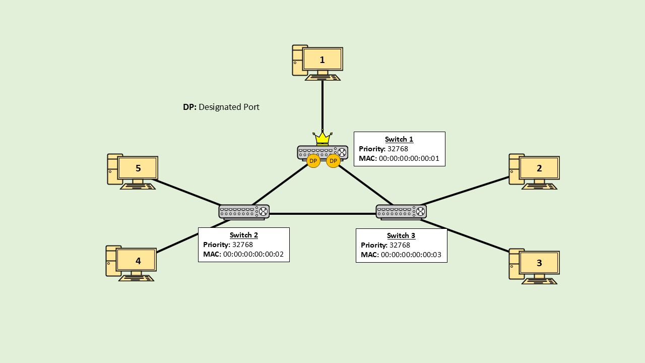
Designated Ports
In our example, Switch 1 will be elected as the root bridge as it has the lowest MAC address (priority is same for all switches). The ports on the root bridge are called designated ports. Designated ports lead data away from the root bridge.
Root Ports
Next, the root ports are configured. Root ports are ports on non-root switches that send data to the root bridge. The port that has the lowest path cost to the root bridge becomes the root port. Links that have high bandwidth have a lower path cost. A non-root switch can only have one root port. The path cost is calculated using the following mapping:
| Speed | STP Cost |
|---|---|
| 10 Mbps | 100 |
| 100 Mbps | 19 |
| 1 Gbps | 4 |
| 10 Gbps | 2 |
Cost Table
Newer revisions of STP use a different cost table. When STP was created, network speeds in excess of 1 Gbps were unfathomable. The original cost table tops out at 10 Gbps. The new table includes costs for networks with bandwidth up to 10 Tbps.
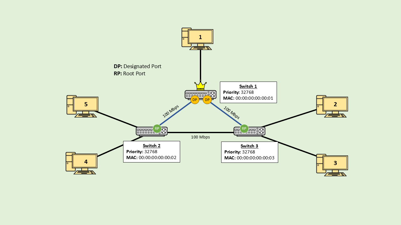
In the above example, I assume that all the links have a bandwidth of 100 Mbps. For switch 2, the link Switch 2 -> Switch 1 has the lowest path cost (19). Similarly, for switch 3, the link Switch 3 -> Switch 1 has the lowest path cost (19). The corresponding port on switch 2 and switch 3 becomes the root port.
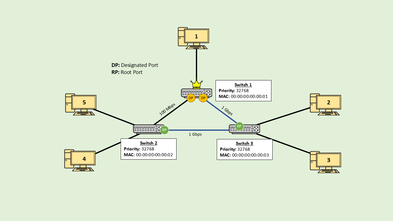
In this example, the links Switch 2 -> Switch 3 and Switch 3 -> Switch 1 have a bandwidth of 1 Gbps. Now, for switch 2, the path with the lowest cost would be Switch 2 → Switch 3 → Switch 1. Even though this is a longer path, the cost for using this path is only 8 (4 + 4), which is lower than 19 the cost for using the link Switch 2 → Switch 1. The port corresponding to this path becomes the root port.
Open & Blocked Ports
Lastly, the ports to be blocked are configured. The port on the switch with the lower BID remains open while the port on the switch with the higher BID is blocked. When a port is blocked, the link/route that originates from that port becomes disabled.
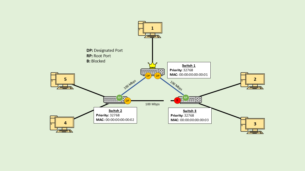
In our example, switch 2 has the lower BID, so the port on switch 2 becomes a designated port. The port on switch 3 is blocked. All data sent to this port is ignored/dropped. This effectively disables the link Swtch 2 -> Switch 3. Since one of the links is disabled, the network no longer contains a loop. And without a loop, a broadcast storm cannot occur.
Ports continue to receive BPDUs even if they’re in the blocked state. Switch 3 receives BPDUs from Switch 2 even though the link between them is disabled for data transmission.
Failure Detection
How do switches learn that a link/router has stopped working? Switches regularly exchange BPDU frames (default every 2 secs). When a switch stops receiving BPDUs from its neighbors, it waits for the max age period (default 20 secs) before declaring the switch dead.
To understand how STP handles failures, let us look at 3 scenarios: one in which the root bridge fails, another in which a non-root switch fails, and one in which a link fails.
Link Failure
Ports on switches are able to sense electric signals. If a link were to get cut/damaged, the port that is connected to the link would stop receiving electric signals. The lack of signal informs the switch that the link is not working. The switch immediately marks the associated port as “down” (inactive). This entire process takes place at layer 1. Once the port is disabled the switch sends a TCN BPDU to the root bridge to trigger a network reconfiguration.
Sometimes the link remains active, and both neighboring switches are operational, but BPDUs are still not received. This can happen due to network misconfigurations and partial hardware issues. This type of failure cannot be identified at layer 1. The switch waits for the max age period and then declares the link on which BPDUs are not being received as dead. The change in topology will cause an STP reconfiguration.
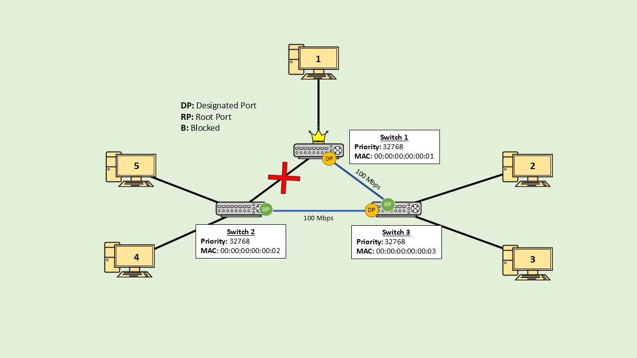
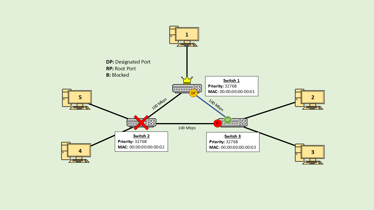
In this example, I am assuming that the link Switch 2 -> Switch 1 has failed. Switch 2 will not receive BPDUs for the root bridge; it will wait for the max age period and then mark the link as dead. Switch 2 will communicate with Switch 3 using the link Switch 2 -> Switch 3. Switch 2 will send a TCN BPDU to switch 3 to notify of the topology change. Switch 2 will set its only functional port as a root port. For switch 2, the link Switch 2 -> Switch 3 -> Switch 1 is now the lowest cost path to the root bridge. The blocked port on Switch 3 will now become a designated port. Because of the redundancy, even though one of the links is down, all the client devices are still able to communicate with each other.
Root Bridge Failure
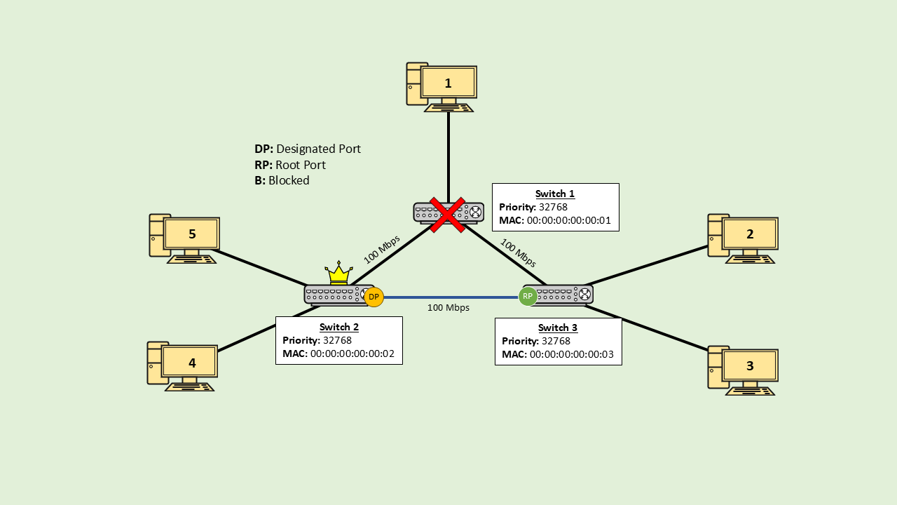
Switch 2 and switch 3 stop receiving BPDUs from the root bridge. They wait for the max age period and then declare the link to the root bridge as dead. Switch 2 and Switch 3 communicate with Switch 2 over the link Swith 2 -> Switch 3; since they both don’t receive CBPDUs, they understand that the root bridge has failed.
Switch 2 and switch 3 share TCN BPDU and understand that a new root bridge has to be elected. The switch with the lowest BID becomes the new root bridge. In our example, switch 2 will become the root bridge. The ports on switch 2 become the designated ports. Next, the non-root switches decide the root ports. The only non-root switch is switch 3, and it only has one port to the root bridge, so this port becomes the root port. Finally, STP decides which ports to block. Since all ports have been configured, no ports need to be blocked.
With the failure of switch 1, there is no way to reach PC 1. PC 1 is completely cut off from the network.
Non-Root Switch Failure
When switch 2 fails, switch 3 stops receiving BPDUs from switch 2. Also, the port on switch 1 and switch 3 that is connected to switch 2 stops receiving electrical signals. From this, switch 3 and switch 1 understand that there is a problem on the link to switch 2. Switch 3 will also stop receiving BPDUs from switch 2 but will continue to receive BPDUs from the root bridge on the link.
Switch 3 will wait for the max age period and, on not receiving any BPDU, will declare the link with switch 2 as dead and send a TCN BPDU to the root bridge. Depending on the network topology, when a non-root switch fails, port reconfiguration could be required. In our example, reconfiguration is not required. With the failure of Switch 2, PC 4 and PC 5 become disconnected from the network.
Types of STP
STP was developed in 1990 and was published as the IEEE 802.1d standard. In 2001, an improved version of STP called RSTP (Rapid STP) was developed, which was published as the 802.1w standard. RSTP has faster convergence. Convergence is the time taken for all the switches to agree on a loop-free topology.
Shortly after, Cisco published their own implementation of STP and RSTP called PVST+ (Per-VLAN Spanning Tree Plus) and RPVST+, respectively. The Cisco implementation added support for spanning tree on VLANs. Cisco devices use PVST+ by default. In PVST, the switch’s priority number includes the VLAN ID.
In RSTP and RPVST+, all switches can generate and forward BPDUs. Furthermore, instead of waiting for the max age period, the switches actively negotiate with their neighbors to quickly determine if any link has stopped working.
In 2002, a version of STP that supported VLANs was created. MSTP (Multiple Spanning Tree Protocol) was published as IEEE 802.1s. If PVST+ is used and there are 50 VLANs, then 50 spanning trees will be created. MSTP groups multiple VLANs in a single spanning tree, so instead of 50, only 3-4 trees would be used.
In 2004, IEEE merged RSTP into the 802.1d standard, which made original STP obsolete.